How Does a Gated Latch Work Inside Digital Circuits
A gated latch is a fundamental building block in digital circuits that stores one bit of data using logic gates and an enable signal. It acts like a gatekeeper, letting data pass only when a control signal tells it to. In automotive systems, gated latches help manage sensor inputs, engine timing, and safety-critical data. Understanding how a gated latch works gives you insight into the electronics that power modern vehicles and countless digital devices.
Digital circuits are everywhere. They run your car’s engine control unit. They manage your anti-lock brakes. They keep your cruise control working smoothly. But inside all of these systems, there is a small but mighty component called a gated latch. If you have ever wondered how digital electronics store and manage tiny bits of information, you are in the right place.
Today, we are going to break down exactly how a gated latch works inside digital circuits. We will look at its inner structure, how the enable signal controls data flow, and why it plays such a big role in automotive electronics. Whether you are a student, a hobbyist, or a curious car owner, this guide will walk you through everything step by step.
Let us start at the very beginning. A gated latch is a type of digital storage element. It holds one bit of data, either a 0 or a 1. Unlike a simple latch, a gated latch adds a control input. This control input is called the enable signal. When the enable signal is active, data can enter and change the stored value. When it is inactive, the latch holds whatever value it already has. Think of it like a door with a lock. The data is inside the room. The enable signal is the key. Without the key, nothing gets in or out.
Key Takeaways
- A gated latch stores binary data temporarily: It holds a 0 or 1 until the enable signal changes.
- The enable signal controls everything: When active, data flows in. When inactive, the latch holds its current value.
- Gated latches differ from flip-flops: Latches respond to level-triggered signals, while flip-flops use edge-triggered signals.
- Automotive systems rely heavily on gated latches: They appear in engine control units, safety sensors, and memory circuits.
- Timing matters enormously: Setup time and hold time determine whether a latch captures data correctly.
- Common mistakes include ignoring propagation delay: This can cause data corruption in fast digital circuits.
- Building a gated latch is straightforward: It uses basic NAND or NOR gates connected in a feedback loop.
📑 Table of Contents
- What Is a Gated Latch and Why Does It Matter?
- The Basic Building Blocks of a Gated Latch
- How the Enable Signal Controls Data Flow
- Gated Latch vs. Flip-Flop: Key Differences
- Timing Concepts: Setup Time, Hold Time, and Propagation Delay
- Gated Latch Applications in Automotive Systems
- How to Build a Simple Gated Latch
- Key Takeaways
What Is a Gated Latch and Why Does It Matter?
A gated latch is one of the simplest memory elements in digital electronics. It belongs to a family of circuits called sequential logic circuits. These circuits do more than just process data. They remember data. That memory capability is what makes computers, cars, and smartphones so powerful.
In automotive systems, the gated latch quietly does its job inside engine control units, transmission controllers, and safety systems. Every time a sensor reads your wheel speed or your engine temperature, a gated latch may be holding that data temporarily before the processor acts on it. Without latches, digital systems would have no short-term memory. They would forget everything the instant a signal changed.
How a Gated Latch Differs from Other Storage Circuits
There are several types of storage elements in digital design. The most common ones are the SR latch, the D latch, and the flip-flop. A basic SR latch has two inputs, set and reset. A gated latch adds a third input, the enable or gate signal. This extra input gives designers precise control over when data is stored.
A flip-flop, on the other hand, changes state only on a clock edge. A gated latch changes state whenever the enable signal is active. This difference matters a lot in circuit design. It affects timing, power consumption, and how reliably data is captured.
The Basic Building Blocks of a Gated Latch
At its core, a gated latch is built from simple logic gates. Most commonly, it uses NAND gates or NOR gates. These gates are combined in a specific way to create a circuit that can store a single bit. Let us look at how this works.
Logic Gates: The Foundation
Logic gates are the smallest building blocks of digital circuits. A NAND gate outputs 0 only when both inputs are 1. A NOR gate outputs 1 only when both inputs are 0. By connecting these gates together in a feedback loop, you create a circuit that can hold a state. This is the basic principle behind every gated latch.
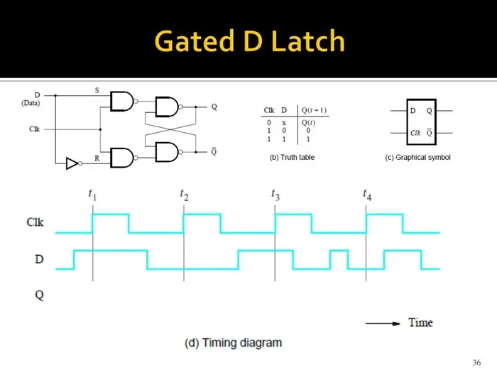
Here is a simple way to think about it. Two NAND gates connected in a cross-feedback loop form a basic latch. Add two more gates controlled by the enable signal, and you have a gated latch. The enable gates act as switches. They decide whether the feedback loop can respond to new input data.
The Role of the Feedback Loop
The feedback loop is what gives the gated latch its memory. When the enable signal is off, the loop keeps the output stable. It does not matter what happens at the inputs. The stored value remains unchanged. This is called data retention. It is the reason a gated latch can hold information even when the input signal disappears.
When the enable signal turns on, the feedback loop opens up. New data can flow through and change the stored value. Once the enable signal turns off again, the loop closes. The new value gets locked in place. This is how a gated latch captures and holds binary data.
How the Enable Signal Controls Data Flow
The enable signal is the heart of how a gated latch operates. It acts like a traffic light for data. Green means data can pass through. Red means data is held in place. Let us break down exactly how this works.
When the Enable Signal Is Active
When the enable signal goes high, the control gates open. The input data reaches the internal feedback loop. If the input is a 1, the latch stores a 1. If the input is a 0, the latch stores a 0. The gated latch captures whatever value is present at its input at that exact moment.
This is why timing is so important. The data must be stable before the enable signal changes. If the data changes too close to the enable signal transition, the latch might capture the wrong value. We will talk more about this in the timing section below.
When the Enable Signal Is Inactive
When the enable signal goes low, the control gates close. The input data is disconnected from the feedback loop. The latch holds its current value. No matter what happens at the input, the stored bit stays the same. This is the holding state.
In automotive circuits, this holding behavior is essential. For example, when an engine control unit reads a sensor value, it captures that value using a gated latch. The latch holds the value steady while the processor performs calculations. If the latch released the value too early, the calculations could be wrong. That could lead to poor engine performance or even safety issues.
A Simple Example of Enable Signal Control
Let us walk through a quick example. Imagine a gated latch with an input labeled D and an enable labeled E. The stored output is labeled Q.
- E is low. Q holds its current value. D can change freely without affecting Q.
- E goes high. D is a 1. The latch captures the 1. Q becomes 1.
- E stays high. D changes to 0. The latch may capture the 0. Q could change to 0.
- E goes low. Q locks in whatever value it has. D no longer matters.
This example shows exactly how the enable signal gates the flow of data into the latch. The name “gated latch” comes directly from this behavior.
Gated Latch vs. Flip-Flop: Key Differences
People often confuse gated latches with flip-flops. Both store one bit of data. Both are essential in digital design. But they work in very different ways. Understanding the difference is important for anyone studying digital circuits or working on automotive electronics.
Level-Triggered vs. Edge-Triggered
A gated latch is level-triggered. This means it responds to the level of the enable signal. When the enable is high, the latch is transparent. Data passes through freely. When the enable is low, the latch holds its value.
A flip-flop is edge-triggered. It only changes state at a specific edge of the clock signal, either the rising edge or the falling edge. Between clock edges, a flip-flop holds its value regardless of input changes.
When to Use Each One
Gated latches are simpler and faster. They use fewer transistors. They are great for temporary data storage and for circuits where speed matters. Flip-flops are more predictable. They avoid the timing problems that can plague latches. Most modern digital systems use a mix of both.
In automotive applications, you will find both types. The engine control unit might use flip-flops for critical timing operations. A body control module might use gated latches for simpler sensor buffering tasks. Each has its place.
Comparison Table: Gated Latch vs. Flip-Flop
| Feature | Gated Latch | Flip-Flop |
|---|---|---|
| Triggering Type | Level-triggered | Edge-triggered |
| Response to Enable Signal | Changes while enable is active | Changes only on clock edge |
| Speed | Faster response | Slightly slower |
| Circuit Complexity | Simpler design | More complex |
| Timing Sensitivity | More sensitive to input changes | Less sensitive |
| Common Use in Automotive | Sensor buffering, temporary storage | Sync circuits, state registers |
| Power Consumption | Lower in simple designs | Higher due to edge detection |
Timing Concepts: Setup Time, Hold Time, and Propagation Delay
Timing is one of the most important aspects of how a gated latch works. If the timing is wrong, the latch may store incorrect data. Let us look at three key timing concepts.
Setup Time
Setup time is the minimum amount of time that the input data must be stable before the enable signal changes. If the data changes too close to the enable transition, the latch might not capture the correct value. Think of it like trying to catch a ball. You need to have your hands ready before the ball arrives.
Hold Time
Hold time is the minimum amount of time that the input data must remain stable after the enable signal changes. If the data changes too soon after the enable transition, the latch might still capture the old value or get confused. This is especially important in fast circuits where signals change quickly.
Propagation Delay
Propagation delay is the time it takes for a change at the input to appear at the output. Every logic gate has a small propagation delay. In a gated latch, this delay determines how fast the latch can respond to new data. In automotive systems, propagation delay matters for real-time control. If a sensor signal takes too long to propagate through the latch, the engine control unit might react too late.
Quick Tips for Understanding Latch Timing
- Always check the datasheet for setup and hold time specifications.
- Keep input signals stable for at least the setup time before the enable edge.
- Keep input signals stable for at least the hold time after the enable edge.
- In automotive circuits, add small delay buffers if signals arrive too quickly.
Gated Latch Applications in Automotive Systems
The automotive industry depends on digital electronics more than ever before. Every modern vehicle contains dozens of electronic control units. Inside each of these units, gated latches play a vital role. Let us explore some of the key applications.
Engine Control Units
The engine control unit, or ECU, is the brain of your car’s engine. It reads data from sensors like the oxygen sensor, the crankshaft position sensor, and the throttle position sensor. A gated latch temporarily holds each sensor reading while the ECU processes it. This ensures that the processor works with a stable, consistent value.
Anti-Lock Braking Systems
Anti-lock braking systems, or ABS, rely on fast and reliable data handling. Wheel speed sensors send signals to the ABS controller. A gated latch captures each sensor pulse at the right moment. This allows the controller to determine when a wheel is about to lock up and adjust the brake pressure accordingly.
Transmission Control Modules
Your car’s transmission shifts gears based on input from various sensors. Vehicle speed, throttle position, and engine load all feed into the transmission control module. Gated latches hold these input values steady during each shift decision. Without them, the transmission might shift at the wrong time or behave erratically.
Safety and Airbag Systems
Airbag systems are safety-critical. They must respond within milliseconds of a collision. A gated latch in the airbag control module holds the crash sensor signal long enough for the processor to confirm the event. This prevents false deployments and ensures the airbag fires only when needed.
Common Mistakes When Working with Gated Latches
- Ignoring enable signal timing: Changing the enable signal too quickly causes data corruption.
- Forgetting about propagation delay: Fast signals may not be captured correctly if the delay is not accounted for.
- Confusing latches with flip-flops: Using a latch where a flip-flop is needed can cause unpredictable behavior in synchronous circuits.
- Not powering the circuit properly: A gated latch needs a stable power supply. Voltage drops can cause the stored value to flip unexpectedly.
- Overlooking noise on input lines: Electrical noise in automotive environments can cause the latch to capture false data.
How to Build a Simple Gated Latch
If you want to truly understand how a gated latch works, try building one. You do not need expensive equipment. A basic breadboard and a few logic gates are all you need.
What You Will Need
- Four NAND gates (a quad NAND gate IC like the 74LS00 works great)
- A breadboard and jumper wires
- A power supply (5V DC)
- Push buttons for input and enable
- LEDs to show the output
Step-by-Step Build
- Place the NAND gate IC on the breadboard and connect the power and ground pins.
- Wire two NAND gates together in a cross-feedback loop. This forms the basic latch core.
- Connect the other two NAND gates as control gates. Tie their inputs to the enable signal.
- Connect your data input to the control gates. Connect the output of the control gates to the feedback loop.
- Add a push button for the enable signal. Add another push button for the data input.
- Connect LEDs to the outputs so you can see the stored value.
- Test the circuit. Press the data button with the enable off. The LED should not change. Then press the enable button. The LED should change to match the input.
Building a gated latch by hand is one of the best ways to understand how it works. You will see firsthand how the enable signal controls data flow and how the feedback loop holds the stored value.
Expert Insight: Why Automotive Engineers Love Gated Latches
Experienced automotive electronics engineers often choose gated latches for simple buffering tasks. They are fast, they use minimal components, and they are easy to design into a circuit. The trade-off is that latches require careful attention to timing. A well-designed gated latch circuit in an automotive ECU can run reliably for the entire life of the vehicle. The key is understanding the timing constraints and designing the circuit to meet them.
Key Takeaways
A gated latch is a simple but essential part of digital circuits. It stores one bit of data and controls when that data can be changed. The enable signal acts as a gate, deciding when new data can enter and when the stored value must be held steady.
In automotive systems, gated latches help engine control units, ABS controllers, and airbag modules work reliably. They hold sensor data steady, prevent false readings, and ensure that critical decisions are made with accurate information.
Understanding how a gated latch works gives you a deeper appreciation for the electronics inside your vehicle. It also builds a strong foundation for anyone interested in digital design, embedded systems, or automotive engineering.
Whether you are building a circuit on a breadboard or designing the next generation of automotive safety systems, the gated latch remains one of the most important tools in your digital design toolkit. Keep experimenting, keep learning, and keep exploring how these tiny circuits make our modern world work.
Frequently Asked Questions
What is the main job of a gated latch?
A gated latch stores one bit of binary data and controls when that data can be changed. The enable signal acts like a gate. When the gate is open, new data can enter. When the gate is closed, the stored value stays the same.
How is a gated latch different from a flip-flop?
A gated latch is level-triggered, meaning it responds while the enable signal is active. A flip-flop is edge-triggered, meaning it only changes state at a specific clock edge. Latches are simpler and faster, while flip-flops are more predictable and reliable in synchronous circuits.
Where are gated latches used in cars?
Gated latches appear in engine control units, anti-lock braking systems, transmission modules, and airbag controllers. They hold sensor data temporarily while the processor makes decisions. They also buffer signals in body control modules and lighting systems.
What happens if the enable signal changes too quickly?
If the enable signal changes too quickly, the gated latch might capture the wrong data. This is called a timing violation. It can happen if the input data changes too close to the enable transition, violating the setup time or hold time requirements of the latch.
Can a gated latch store data permanently?
No, a gated latch stores data only temporarily. It holds a value as long as power is supplied and the enable signal conditions are met. If power is removed, the stored value is lost. For permanent storage, other types of memory circuits are used.
Do I need advanced electronics knowledge to understand gated latches?
Not at all. The basic concept of a gated latch is quite simple. It stores a 0 or a 1 and uses an enable signal to control when data changes. With a basic understanding of logic gates and a simple breadboard build, anyone can grasp how a gated latch works inside digital circuits.
=== CONCLUSION ===
The gated latch may be small, but its role in digital circuits is enormous. It provides the short-term memory that every digital system needs. From holding a single sensor reading in your car’s engine control unit to buffering data in complex safety systems, the gated latch does its job quietly and reliably every single day.
Understanding how a gated latch works opens the door to a deeper knowledge of digital electronics. You now know how the enable signal controls data flow, how the feedback loop stores a bit, and why timing matters so much. You also know how these circuits are used in real automotive applications.
The next time you start your car or feel your ABS kick in during an emergency stop, remember the tiny gated latch working behind the scenes. It is one of the unsung heroes of modern electronics. Keep exploring, keep building, and never stop learning about the circuits that power the world around you.